
Join 60,000+ competitive exam aspirants
or with email
Your Cart
Subtotal₹0
Total₹0
Examoogle • User • info@examoogle.com • EE-2024-8821
Chapter 1 of 12 • Page 1 of 248🔒 Protected PDF • Watermarked
Join 60,000+ competitive exam aspirants
What does the given circuit symbol represent?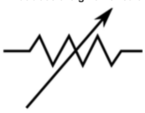
Fixed resistor
Variable resistor (Rheostat)
Potentiometer
Capacitor
Fixed resistor
The given circuit symbol represents a variable resistor, commonly known as a rheostat. It is an electrical component used to control the flow of current in a circuit by changing the resistance without interrupting the electrical connection.
The given circuit symbol represents a variable resistor, commonly known as a rheostat. It is an electrical component used to control the flow of current in a circuit by changing the resistance without interrupting the electrical connection.
A rheostat is like a water valve in a plumbing system. By turning the handle, you restrict the opening, increasing resistance to water flow (less water) or opening it wide to decrease resistance (more water), just as a rheostat controls electrical 'flow'.
V=I×R — Ohm's Law, demonstrating the relationship between Voltage, Current, and Resistance.
R=ρAL — Formula for resistance, where L is length (the rheostat changes this length).
A rheostat functions by moving a sliding contact (wiper) along a resistive element (often a coil of wire). By increasing or decreasing the length of the resistive path through which the current flows, the rheostat alters the total circuit resistance according to Ohm's Law (V=I×R). Consequently, as resistance R is changed, the current I flowing through the circuit varies while the supply voltage V remains constant.
The arrow through the resistor symbol denotes 'variability'.
Rheostats are used for motor speed control, lighting dimmers, and calibration equipment.
A potentiometer is a related device, often used as a voltage divider.
Allows smooth, continuous adjustment of current.
Simple, rugged design suitable for high power applications.
Energy is dissipated as heat, leading to lower efficiency compared to electronic switching controllers (like PWM).
Can be bulky for high-current applications.
Dimming of incandescent lights.
Speed control of small DC motors in laboratory settings.
Variable load testing in power supplies.
Option B represents a standard conducting wire.
Option C represents a DC voltage source (battery).
Option D typically depicts a switch symbol (two dots with a bridging arm).
A is correct — The diagram shows a zigzag resistor symbol with an arrow, which is the international symbol for a variable resistance or rheostat.
Always look for the diagonal arrow in a circuit symbol; it almost universally indicates a variable component (e.g., variable capacitor, variable resistor).
Get instant step-by-step AI explanations, full shift Previous Year Papers (SSC GD, RRB, SSC JE), and regional rank analysis on the official Examoogle App.
 Free Download • 100K+ Aspirants